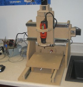
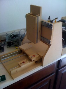
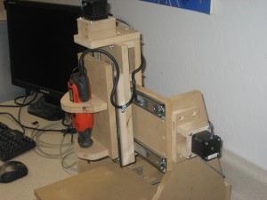
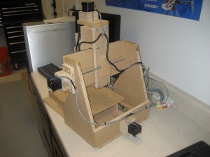
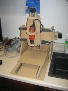
Every serious modeler needs a CNC router! Here is a simple How-to for a cheap desktop machine I made for a friend using re-cycled electronics. You can buy NEMA 17 motors on ebay for less than $10 each and build or buy a cheap driver board. The cost of the materials for the build (minus electronics) should easily be under $100 and probably closer to $50. Software is another issue but there are several free programs that will do a good job for most 2-2.5 D stuff. Of course check out Mach3/LazyCAM for the CAM part and DraftSight for the CAD part.
I saw some posts on drawer slides and thought it might be a cheap easy way to make a small desktop machine for hobbyist. As it turns out, you could probably order some drill rods and nylon bearings cheaper but I was interested in using all hardware store stuff and NOT mail ordering anything. I wanted to hold about .010. This is half the width of a typical .5mm mechanical pencil line. I figured this was plenty good enough for typical hobby stuff and PC boards. Measuring the finished machine shows around .005 repeatability which is plenty good for model airplane bulkheads and such.
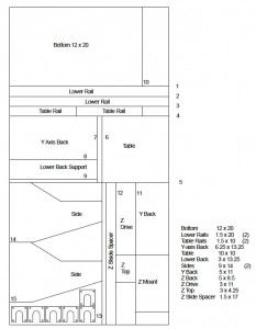
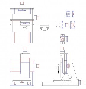
Here is the DXF file I threw together and a few sketches.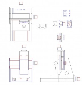

The idea was to have a simple low-cost machine that had a small footprint. Using a 2 x 4 piece of 5/8 MDF available at the local Home improvement store yielded CNC3. This will give you a 9 x 9 x 4 cut area. On this build, we set the limits at 8.5 x 8.5 x 3.5. You could probably extend the bottom 2 inches. Just re-think the actual rail size and shuffle them around a little to make the table the 2 inches bigger also. Regardless, be sure you follow the cut order or think about it before you start cutting to make sure the material works out.
The hole in the side of CNC2 was originally a target to line up the drilling for the Y stepper motor. I ended up NOT using it. After assembly, I used the Y axis screw to target the center of the stepper motor mount. After marking the location, I just removed the side and drilled the hole. I used countersink #8 screws for basic assemble. Make sure you drill the pilot hole deeper than needed and clear out the sawdust to avoid splitting the wood
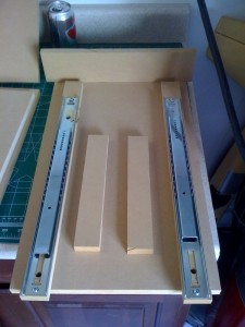
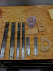
The slides need to be cut down. Take them apart to do this. I found they had too much friction and ended up removing most of the balls. I left the first two on each end. This made for a smooth movement that still didn’t have any perceptible slop. There are as many opinions how to mount drawer slides as there are builders. I just wanted something quick and simple. Remember, .010 was the goal. Once each axis is assembled, you won’t feel any slop in the slides.
Above we are preparing parts. You can see the spindle mount and some modified slides. These were bought at Lowe’s for less than $5 each. Think about how you assemble each axis as you go. We mounted one end, slid the axis back and forth to make sure the rails were aligned, then drilled the other end. Once secure, you can add a few screws if you like. You will need to drill new holes in the slides. We used (4) #6 pan head screws for each one.
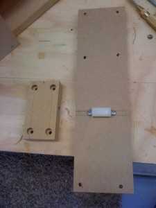
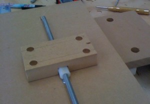
Here is the drive nut. We used a 1/4 x 20 Nylon Coupler from Ace hardware ($ .99). When threaded on the rod, it gets snug enough where there is no real perceptible slop or backlash. Looking at the drawing, you need to sand about 1/8 inch off one side along the length. I kept checking this until it made the retainer block stand off the mounting surface about .010-020. This slight interference will assure a tight fit. I used some scrap 3/4 MDF for the nut retainer shown above. I was woried about the 5/8 cracking. I used a dremel tool with a sanding drum to put a small notch in each end of the nylon nut. This is for the pan head screws. I did one end, installed the screws, and sanded the other end until I got a nice ‘snap’ fit of the nut between the screws as shown in the photo on the left. The block in the photo on the right is NOT screwed on. I just took the photo to show how it looks. Center the block before screwing it down. Its a nice simple cheap drive nut requiring minimal fabrication.
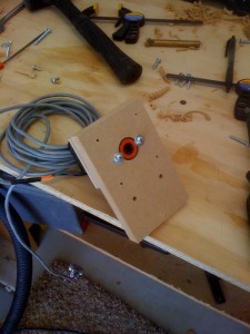
This is a skate bearing. You can probably get your local skate shop to give you 3. I paid $7 for a package of 8. I didn’t care about the quality as the crappiest skate bearing is overkill for this application. I used a 7/8 spade wood bit to drill the countersink. Leave the bearing just a shade prode (above) the surface. Don’t put the retainer wood screws too close. They will deform the outer race and cause the bearing to run rough. Move them out a little and use washers. You can see the photo on the right does NOT have the stepper hole drilled in it yet.
The free end of the 1/4-20 rod was just left, well free…For this size machine and theses low speeds, it works just fine. It also makes alignment less critical between the motor, bearing, and drive nut. any minor misalignment just causes the free end of the drive screw to whip around. The worst axis on this machine whips about a 1/2 inch circle at its worse. Not a big deal….
Ace Hardware has a 1/4 to 5/16 nylon bushing you will need to center the 1/4-20 threaded rod in the 5/16 skate bearing ($.49). The 1/4-20 rod was still be a bit sloppy so I wrapped tape around it until it was a snug fit. I used lock nuts on either side of the bearing to lock the rod from moving. I used 1/4 Fuel Injector hose from the auto parts store and hose clams as couplers. It allows a slight amount of flex while still driving with minimal (no) slop. For a small machine jogging at 30 IPM, this is fine.
Well I know it wasn’t very detailed but with the photos, drawings, and some basic building skills, you should be able to build one. The motor mounts were sized for some metric equivalents of NEMA 17’s so you may have to adjust them a little for your motors. The last few photos are higher resolution to help with any details. E-mail me if you have any questions and I’ll try to help.
Scott

