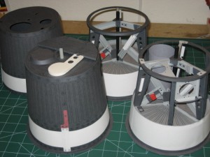
 The paper model is explained in the FAQ section. Its a basis to verify design and fit of full size parts. The model does not include the internal plumbing or wiring. Its a challenging build with over 100 pages to print on various weights and colors of card stock containing over 1000 parts. It may get updated in the future but for now its a pretty cool display!
First up is the Antenna Fairing as shown above. It was a challenging place to start (hence the multiples above). It’s an odd part that most people don’t get to see as the flown capsules lost theirs during descent. Its also interesting to note that many models and artist renderings show a small cone on top of the Antenna Fairing. This was actually part of the escape tower and left with it just before orbital insertion. The de-stabilizing flap opens to expose one of the horizon scanners required in orbit.
I have had a few complaints about print format. Mostly, people have had trouble with the printer cutting off or not printing edges. If you configure your PDF and printer settings properly, you can print the entire page. It may be a bit of a struggle but you can get it to work. Some of the parts need every bit of paper. If you can’t do it, you can just extend the lines manually with a pencil and ruler before cutting the parts out.
The files are presented in various formats with later ones being zipped into entire folders. Be patient…
Instruction _____ Instruction_page14
Card_Antenna1 __ Card_Antenna2 __ Card_Antenna3 __ Card_Antenna4
Card_Structure1 __ Card_Structure2 __ Card_Structure3 __ Card_Structure4
